- Overview
- / BAR System
- /Batten grid Z140/Z280
BAR System Equipment

Batten grid Z140/Z280
LED Light strip inserts with steel plate fitting, white, 2 plastic cabinet locks for a quick assembly without tools, 2 drop guards on spring, earth contacts as a standby for simplified wiring process. Halogen-free wiring 5 x 1,5 mm2, plug in terminal 5 x 1,5 mm2.
All length specifications are nominal dimensions.
Between the light strips must be taken an additional 2 mm gap (tolerance), in the planning of light bands.
Between the light strips must be taken an additional 2 mm gap (tolerance), in the planning of light bands.
| M02 0311.B | Z280 |
|
560 mm | M02 0311.B / Datasheet | M02 0311.B / LDT file | M02 0311.B / LVK image | M02 0311.B / Dimension drawing | ||||
|---|---|---|---|---|---|---|---|---|---|---|---|
| M03 0311.B | Z280 |
|
840 mm | M03 0311.B / Datasheet | M03 0311.B / LDT file | M03 0311.B / LVK image | M03 0311.B / Dimension drawing | ||||
| M04 0311.B | Z280 |
|
1120 mm | M04 0311.B / Datasheet | M04 0311.B / LDT file | M04 0311.B / LVK image | M04 0311.B / Dimension drawing | ||||
| M05 0311.B | Z280 |
|
1400 mm | M05 0311.B / Datasheet | M05 0311.B / LDT file | M05 0311.B / LVK image | M05 0311.B / Dimension drawing | ||||
| M06 0311.B | Z280 |
|
1680 mm | M06 0311.B / Datasheet | M06 0311.B / LDT file | M06 0311.B / LVK image | M06 0311.B / Dimension drawing | ||||
| M07 0311.B | Z140 |
|
700 mm | M07 0311.B / Datasheet | M07 0311.B / LDT file | M07 0311.B / LVK image | M07 0311.B / Dimension drawing | ||||
| M09 0311.B | Z140 |
|
980 mm | M09 0311.B / Datasheet | M09 0311.B / LDT file | M09 0311.B / LVK image | M09 0311.B / Dimension drawing | ||||
Between the light strips must be taken an additional 2 mm gap (tolerance), in the planning of light bands.
| M12 0311.B | Z280 |
|
560 mm | M12 0311.B / Datasheet | M12 0311.B / LDT file | M12 0311.B / LVK image | M12 0311.B / Dimension drawing | ||||
|---|---|---|---|---|---|---|---|---|---|---|---|
| M13 0311.B | Z280 |
|
840 mm | M13 0311.B / Datasheet | M13 0311.B / LDT file | M13 0311.B / LVK image | M13 0311.B / Dimension drawing | ||||
| M14 0311.B | Z280 |
|
1120 mm | M14 0311.B / Datasheet | M14 0311.B / LDT file | M14 0311.B / LVK image | M14 0311.B / Dimension drawing | ||||
| M15 0311.B | Z280 |
|
1400 mm | M15 0311.B / Datasheet | M15 0311.B / LDT file | M15 0311.B / LVK image | M15 0311.B / Dimension drawing | ||||
| M16 0311.B | Z280 |
|
1680 mm | M16 0311.B / Datasheet | M16 0311.B / LDT file | M16 0311.B / LVK image | M16 0311.B / Dimension drawing | ||||
| M17 0311.B | Z140 |
|
700 mm | M17 0311.B / Datasheet | M17 0311.B / LDT file | M17 0311.B / LVK image | M17 0311.B / Dimension drawing | ||||
| M19 0311.B | Z140 |
|
980 mm | M19 0311.B / Datasheet | M19 0311.B / LDT file | M19 0311.B / LVK image | M19 0311.B / Dimension drawing | ||||
Between the light strips must be taken an additional 2 mm gap (tolerance), in the planning of light bands.
| M02 0411.B | Z280 |
|
560 mm | M02 0411.B / Datasheet | M02 0411.B / LDT file | M02 0411.B / LVK image | M02 0411.B / Dimension drawing | ||||
|---|---|---|---|---|---|---|---|---|---|---|---|
| M03 0411.B | Z280 |
|
840 mm | M03 0411.B / Datasheet | M03 0411.B / LDT file | M03 0411.B / LVK image | M03 0411.B / Dimension drawing | ||||
| M04 0411.B | Z280 |
|
1120 mm | M04 0411.B / Datasheet | M04 0411.B / LDT file | M04 0411.B / LVK image | M04 0411.B / Dimension drawing | ||||
| M05 0411.B | Z280 |
|
1400 mm | M05 0411.B / Datasheet | M05 0411.B / LDT file | M05 0411.B / LVK image | M05 0411.B / Dimension drawing | ||||
| M06 0411.B | Z280 |
|
1680 mm | M06 0411.B / Datasheet | M06 0411.B / LDT file | M06 0411.B / LVK image | M06 0411.B / Dimension drawing | ||||
| M07 0411.B | Z140 |
|
700 mm | M07 0411.B / Datasheet | M07 0411.B / LDT file | M07 0411.B / LVK image | M07 0411.B / Dimension drawing | ||||
| M09 0411.B | Z140 |
|
980 mm | M09 0411.B / Datasheet | M09 0411.B / LDT file | M09 0411.B / LVK image | M09 0411.B / Dimension drawing | ||||
Between the light strips must be taken an additional 2 mm gap (tolerance), in the planning of light bands.
| M12 0411.B | Z280 |
|
560 mm | M12 0411.B / Datasheet | M12 0411.B / LDT file | M12 0411.B / LVK image | M12 0411.B / Dimension drawing | ||||
|---|---|---|---|---|---|---|---|---|---|---|---|
| M13 0411.B | Z280 |
|
840 mm | M13 0411.B / Datasheet | M13 0411.B / LDT file | M13 0411.B / LVK image | M13 0411.B / Dimension drawing | ||||
| M14 0411.B | Z280 |
|
1120 mm | M14 0411.B / Datasheet | M14 0411.B / LDT file | M14 0411.B / LVK image | M14 0411.B / Dimension drawing | ||||
| M15 0411.B | Z280 |
|
1400 mm | M15 0411.B / Datasheet | M15 0411.B / LDT file | M15 0411.B / LVK image | M15 0411.B / Dimension drawing | ||||
| M16 0411.B | Z280 |
|
1680 mm | M16 0411.B / Datasheet | M16 0411.B / LDT file | M16 0411.B / LVK image | M16 0411.B / Dimension drawing | ||||
| M17 0411.B | Z140 |
|
700 mm | M17 0411.B / Datasheet | M17 0411.B / LDT file | M17 0411.B / LVK image | M17 0411.B / Dimension drawing | ||||
| M19 0411.B | Z140 |
|
980 mm | M19 0411.B / Datasheet | M19 0411.B / LDT file | M19 0411.B / LVK image | M19 0411.B / Dimension drawing | ||||
Between the light strips must be taken an additional 2 mm gap (tolerance), in the planning of light bands.
| M02 0313.B | Z280 |
|
560 mm | M02 0313.B / Datasheet | M02 0313.B / LDT file | M02 0313.B / LVK image | M02 0313.B / Dimension drawing | ||||
|---|---|---|---|---|---|---|---|---|---|---|---|
| M03 0313.B | Z280 |
|
840 mm | M03 0313.B / Datasheet | M03 0313.B / LDT file | M03 0313.B / LVK image | M03 0313.B / Dimension drawing | ||||
| M04 0313.B | Z280 |
|
1120 mm | M04 0313.B / Datasheet | M04 0313.B / LDT file | M04 0313.B / LVK image | M04 0313.B / Dimension drawing | ||||
| M05 0313.B | Z280 |
|
1400 mm | M05 0313.B / Datasheet | M05 0313.B / LDT file | M05 0313.B / LVK image | M05 0313.B / Dimension drawing | ||||
| M06 0313.B | Z280 |
|
1680 mm | M06 0313.B / Datasheet | M06 0313.B / LDT file | M06 0313.B / LVK image | M06 0313.B / Dimension drawing | ||||
| M07 0313.B | Z140 |
|
700 mm | M07 0313.B / Datasheet | M07 0313.B / LDT file | M07 0313.B / LVK image | M07 0313.B / Dimension drawing | ||||
| M09 0313.B | Z140 |
|
980 mm | M09 0313.B / Datasheet | M09 0313.B / LDT file | M09 0313.B / LVK image | M09 0313.B / Dimension drawing | ||||
Between the light strips must be taken an additional 2 mm gap (tolerance), in the planning of light bands.
| M12 0313.B | Z280 |
|
560 mm | M12 0313.B / Datasheet | M12 0313.B / LDT file | M12 0313.B / LVK image | M12 0313.B / Dimension drawing | ||||
|---|---|---|---|---|---|---|---|---|---|---|---|
| M13 0313.B | Z280 |
|
840 mm | M13 0313.B / Datasheet | M13 0313.B / LDT file | M13 0313.B / LVK image | M13 0313.B / Dimension drawing | ||||
| M14 0313.B | Z280 |
|
1120 mm | M14 0313.B / Datasheet | M14 0313.B / LDT file | M14 0313.B / LVK image | M14 0313.B / Dimension drawing | ||||
| M15 0313.B | Z280 |
|
1400 mm | M15 0313.B / Datasheet | M15 0313.B / LDT file | M15 0313.B / LVK image | M15 0313.B / Dimension drawing | ||||
| M16 0313.B | Z280 |
|
1680 mm | M16 0313.B / Datasheet | M16 0313.B / LDT file | M16 0313.B / LVK image | M16 0313.B / Dimension drawing | ||||
| M17 0313.B | Z140 |
|
700 mm | M17 0313.B / Datasheet | M17 0313.B / LDT file | M17 0313.B / LVK image | M17 0313.B / Dimension drawing | ||||
| M19 0313.B | Z140 |
|
980 mm | M19 0313.B / Datasheet | M19 0313.B / LDT file | M19 0313.B / LVK image | M19 0313.B / Dimension drawing | ||||
Between the light strips must be taken an additional 2 mm gap (tolerance), in the planning of light bands.
| M02 0413.B | Z280 |
|
560 mm | M02 0413.B / Datasheet | M02 0413.B / LDT file | M02 0413.B / LVK image | M02 0413.B / Dimension drawing | ||||
|---|---|---|---|---|---|---|---|---|---|---|---|
| M03 0413.B | Z280 |
|
840 mm | M03 0413.B / Datasheet | M03 0413.B / LDT file | M03 0413.B / LVK image | M03 0413.B / Dimension drawing | ||||
| M04 0413.B | Z280 |
|
1120 mm | M04 0413.B / Datasheet | M04 0413.B / LDT file | M04 0413.B / LVK image | M04 0413.B / Dimension drawing | ||||
| M05 0413.B | Z280 |
|
1400 mm | M05 0413.B / Datasheet | M05 0413.B / LDT file | M05 0413.B / LVK image | M05 0413.B / Dimension drawing | ||||
| M06 0413.B | Z280 |
|
1680 mm | M06 0413.B / Datasheet | M06 0413.B / LDT file | M06 0413.B / LVK image | M06 0413.B / Dimension drawing | ||||
| M07 0413.B | Z140 |
|
700 mm | M07 0413.B / Datasheet | M07 0413.B / LDT file | M07 0413.B / LVK image | M07 0413.B / Dimension drawing | ||||
| M09 0413.B | Z140 |
|
980 mm | M09 0413.B / Datasheet | M09 0413.B / LDT file | M09 0413.B / LVK image | M09 0413.B / Dimension drawing | ||||
Between the light strips must be taken an additional 2 mm gap (tolerance), in the planning of light bands.
| M12 0413.B | Z280 |
|
560 mm | M12 0413.B / Datasheet | M12 0413.B / LDT file | M12 0413.B / LVK image | M12 0413.B / Dimension drawing | ||||
|---|---|---|---|---|---|---|---|---|---|---|---|
| M13 0413.B | Z280 |
|
840 mm | M13 0413.B / Datasheet | M13 0413.B / LDT file | M13 0413.B / LVK image | M13 0413.B / Dimension drawing | ||||
| M14 0413.B | Z280 |
|
1120 mm | M14 0413.B / Datasheet | M14 0413.B / LDT file | M14 0413.B / LVK image | M14 0413.B / Dimension drawing | ||||
| M15 0413.B | Z280 |
|
1400 mm | M15 0413.B / Datasheet | M15 0413.B / LDT file | M15 0413.B / LVK image | M15 0413.B / Dimension drawing | ||||
| M16 0413.B | Z280 |
|
1680 mm | M16 0413.B / Datasheet | M16 0413.B / LDT file | M16 0413.B / LVK image | M16 0413.B / Dimension drawing | ||||
| M17 0413.B | Z140 |
|
700 mm | M17 0413.B / Datasheet | M17 0413.B / LDT file | M17 0413.B / LVK image | M17 0413.B / Dimension drawing | ||||
| M19 0413.B | Z140 |
|
980 mm | M19 0413.B / Datasheet | M19 0413.B / LDT file | M19 0413.B / LVK image | M19 0413.B / Dimension drawing | ||||

Umfangreiches Baukastensystem
Mit dem BAR System lassen sich eine Vielzahl an Beleuchtungslösungen für unterschiedliche Anwendungsbereiche realisieren.
Zur Auswahl stehen:
Drei Profilvarianten als Anbau- und Pendellösungen direkt- und direkt/indirekt strahlend sowie LED- und Eutrac-Stromschieneneinsätze und diverse Optiken.

Perfektion bis ins kleinste Detail
Wie für Alteme üblich, ist auch bei BAR jedes kleinste Detail durchdacht und präzise ausgeführt. Alle Abdeckungen werden absolut homogen ausgeleuchtet. Die Alluminium-Endplatten gewährleiten einen sauberen Abschluss aller Profile.
| Mounting instructions |
manual MM01 BAR
|
|---|

BAR LED D End plate
Solid aluminum, machined, chemically frosted and plain anodised, with internal screw mounting and centering. Foam molding as a light barrier
SHOW
BAR LED I End plate
Solid aluminum, machined, chemically frosted and plain anodised, with internal screw mounting and centering. Foam molding as a light barrier
SHOW
BAR LED D+I Connector
Connector in extruded aluminium, with 4 M4 setscrews for fixture to profile. T and X connectors available on request.
SHOW
BAR LED Swivel mounting bracket large
For ceiling thicknesses s=0–25 mm. Strap stainless steel with threaded sleeve and pivot/locking screw M5, galvanized. Minimum installation depth results from bracket height and strength of the ceiling panel. If Installation depth below 115 mm needs fixing screw site be shortened.
SHOW
BAR LED Swivel mounting bracket small
For ceiling thicknesses s=25–50 mm. Strap stainless steel with threaded sleeve and pivot/locking screw M5, galvanized. Minimum installation depth results from bracket height and strength of the ceiling panel. If Installation depth below 115 mm needs fixing screw site be shortened.
SHOW
BAR LED D+I 90° connector
90° connector in blank aluminium, with 2x3 screws for fixture to profile
SHOW
BAR LED D+I Swivel connector 0-90°
Swivel connector 0-90° in blank aluminium, with 2x3 screws for fixture to profile
SHOW
BAR LED D+I Level connector 90°–0°–90°
Level connector 90°–0°–90° in blank aluminium, with 2x2 screws for fixture to profile
SHOW
BAR LED D Suspension cable
Suspension cable ceiling barrel in nickel-plated steel. Susp. cable Ø 1.5 mm, L 2500 mm, continuously adjustable in height, sliding in luminaire profile. Mounting distance max. 1500 mm.
SHOW
BAR LED I Suspension cable
Suspension cable ceiling barrel in nickelplated steel. Suspension cable Ø 1.5 mm, L 2500 mm, continuously adjustable in height. Profile bracket in nickel-plated steel, sliding in luminaire profile. Special lengths of cover indirect opal necessary. Mounting distance max. 1500 mm.
SHOW
BAR LED D Ceiling mounting kit
Ceiling mounting kit in aluminium, chemically mat-finished and plain anodised, sliding in luminaire profile. Mounting distance max. 1500 mm.
SHOW
BAR LED D Wall mounting kit
Wall mounting kit in aluminium, chemically mat-finished and plain anodised, with slots for wall and profile adjustment, sliding in luminaire profile. Mounting distance max. 1500 mm.
SHOW
BAR LED I Wall mounting kit
Clamping profile Aluminium chemically matted and plain anodised. Mounting plate raw aluminum with two slots for easy adjustment
SHOW
BAR LED D+I+E Slide stop
For vertical installation and mounting inclined from an angle of> 10 ° is necessary. Screwed and fixed with two screws.
SHOW
BAR LED D Strain relief set
Through two superimposed, opposite the profile sheets be screwed the rotation is ensured.
SHOW
BAR LED I Strain relief set
Through two M4x40 screws, the strain relief is attached to the profile. In addition, an opal diffuser l = 200mm sent along with clipping to perform the cable. The cover can be cut on site to the gewünschteLänge.
SHOW
BAR LED Wiring extension for blank cover
Halogen-free wiring extension 5x1.5 mm2, color coded for on / off or Dali version, incl. 5 Connection terminals All lengths are nominal mass.
SHOW
Power cable 3x1.5mm2 transparent with Flex Clips, L 3000mm
Cores individually colour coded Transparent fastening clips to fix the cable to the suspension.
SHOW
Power cable 5x1.5mm2 transparent with Flex Clips, L 3000mm,
Cores individually colour coded Transparent fastening clips to fix the cable to the suspension.
SHOW
Ceiling canopy with feeder, round, colorless anodised
Chemically matted and natural anodised, with internal screw fastening, floating clips for a simplified connection. Power cable must be ordered separately. Size: Ø80 x 22mm
SHOW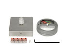
Ceiling canopy with feeder, square, colorless anodised
Chemically matted and natural anodised, with internal screw fastening, floating clips for a simplified connection. Power cable must be ordered separately. Size: 80 x 80 x 22mm
SHOW